Top Guidelines Of Wedge Barriers
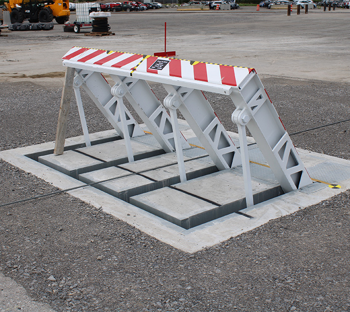
In the following discussion, recommendation is made to a surface of a structure to which the wedge-style obstacle is mounted. In the illustrated embodiments, the upper side of the anchor is substantially flush with the surface of the foundation. In such embodiments, the wedge-style barrier may be installed directly to the surface of the structure. Nevertheless, in other personifications, the top side of the anchor might be somewhat elevated above the surface area of the foundation or a little recessed below the surface area of the foundation. 1 is a front perspective sight of an embodiment of a surface-mounted wedge-style barrier 10. As revealed, the barrier 10 is installed to a surface area 12 of a foundation 14(e. g., a superficial foundation ). The foundation

14 and the surface 12 surface area which the barrier 10 obstacle secured may safeguarded might from concrete. 2, the obstacle 10 is installed to or includes an anchor or subframe (e. g., support 30 displayed in FIG. 2 )secured underneath the surface area 12. The bather 10 may be bolted to the support or protected to the support by various other mechanical fasteners. In the illustrated personification, the obstacle 10 consists of a wedge plate 16, that includes a part that is substantially parallel with the surface 12 when the obstacle 10 remains in the retracted setting. Simply put, automobiles or people may pass over the obstacle 10 when the obstacle 10 remains in the retracted setting and experience minor altitude relative to the surface 12 while on the barrier 10. As gone over carefully listed below, when the barrier 10 remains in the released placement, the wedge plate 16 is held and sustained in an elevated placement by a training mechanism of the barrier 10. Furthermore, the elements 18 may be bolted or otherwise mechanically combined to each other. In this way, repair or substitute of one or even more parts 18 might be streamlined and structured. That is, fixing or replacement of single parts
18 may be Source done quicker, easily, and expense properly. FIG. In certain personifications, the support 30 may be a steel frame including plates, light beams(e. g., I-beams ), and/or various other structures that are protected within the structure 14, which might be concrete. At the surface 12, an upper side 28 of the anchor 30 might be at the very least partly subjected
, thus enabling the attachment of the obstacle 10 to the anchor 30. g., threaded openings)in one or even more beam of lights or plates of the support 30 may be subjected to the surface 12. In this fashion, screws 32 or various other mechanical bolts might be made use of to protect the obstacle 10 to the anchor 30. As the barrier 10 is placed to the surface area 12 of the structure 14, collection of particles and other product below the obstacle might be reduced, and parts of the bather 10 may not be exposed to listed below grade environments. As shown by referral character 52, the lifting mechanism 50 important site consists of parts got rid of beneath the wedge plate 16. For instance, the elements 52 under the wedge plate 16 may include an electromechanical actuator, a camera, several cam surface areas, and so forth. In addition, the lifting device 50 includes a spring setting up 54
The springtime rod 58 is combined to a web cam(e. g., webcam 80 shown in FIG. 4) of the lifting system 50. The springtimes 60 disposed about the spring pole 58 are kept in compression by spring supports 62, including a taken care of springtime support 64. That is, the set spring support 64 is dealt with about the structure 14 and the remainder of the bather 10.
The Facts About Wedge Barriers Uncovered
The staying pressure applied to
the cam camera deploy release wedge plate 16 may might provided supplied an electromechanical actuator 84 or other actuator. The springtime assembly 54 and the actuator 84(e. Wedge Barriers. g., electromechanical actuator)might operate with each other to translate the camera and raise the wedge plate 16.
As mentioned over, in the deployed position, the wedge plate 16 offers to obstruct gain access to or traveling beyond the obstacle 10. The obstacle 10(e. g., the wedge plate 16 )may block pedestrians or automobiles from accessing a building or pathway. If a vehicle is taking a trip in the direction of the released wedge plate 16(e. For instance, in one scenario, the safety legs 86 may be prolonged duringmaintenance of the this link barrier 10.